
D2Denny
-
Posts
99 -
Joined
-
Last visited
-
Days Won
5
Content Type
Profiles
Forums
Gallery
Events
Blogs
BMT Wiki
Collections
Store
Everything posted by D2Denny
-
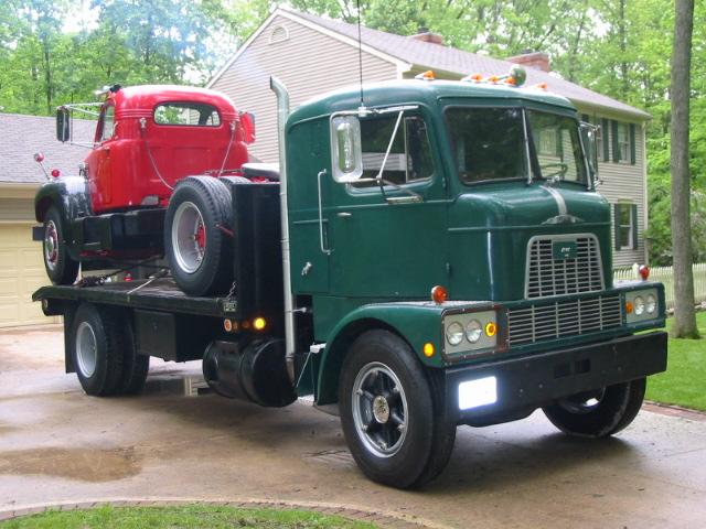
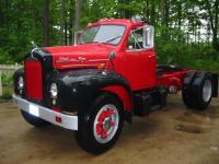
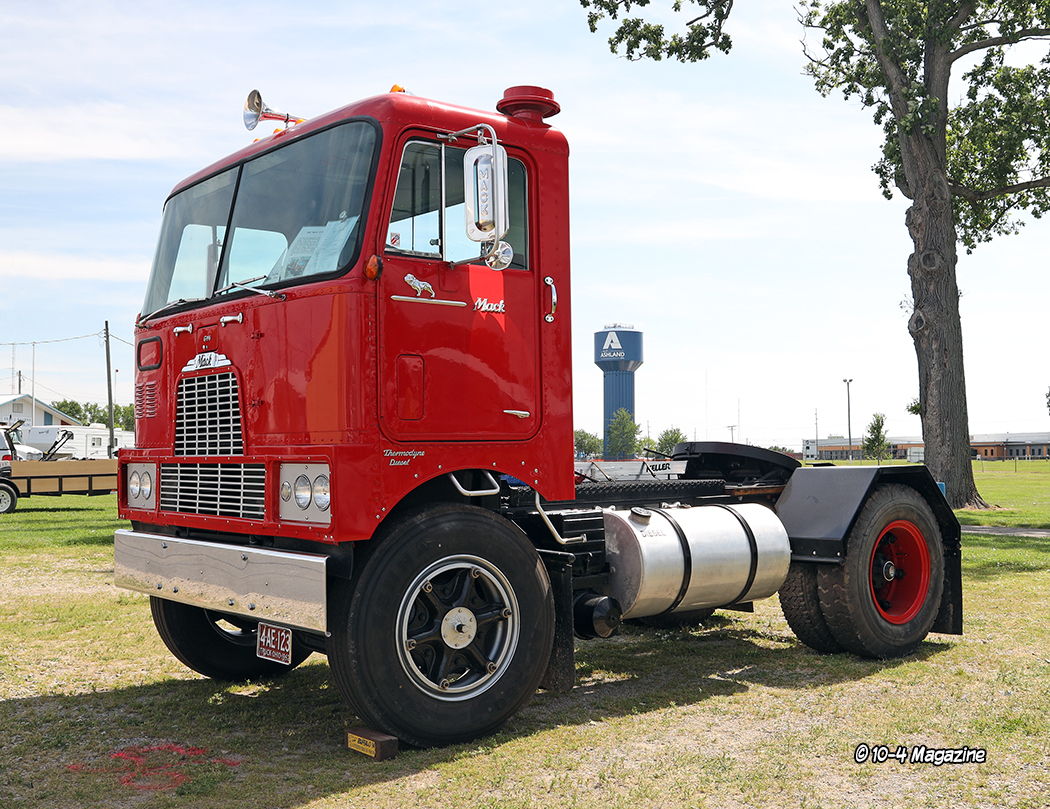
Pulled a 31 Ford A Tudor body off the frame to prep the chassis for a flathead V8, 39 trans and juice brake 40 banjo rear. Ran out of room on the shop floor to store the body so now I have a 4 door Mack G-75!
.thumb.jpg.973be12dfa3ce74fa079428c1c894a80.jpg)
- 1 reply
-
- 11
-

-

-
"Bad" driver and the B Model
D2Denny replied to D2Denny's topic in Antique and Classic Mack Trucks General Discussion
Films were made by Highway Safety Films out of Mansfield, Ohio. Photos and films were real. They had freelance photographers ride with the Police, Sheriff, and ambulances called to accident scenes around the Mansfield area. They were in business late 50's to the early 70's. They also got involved with porno films, and some illegal sex crime surveillance police films. The woman that was in charge of the Mansfield operation mysteriously died toward the end of their run. -
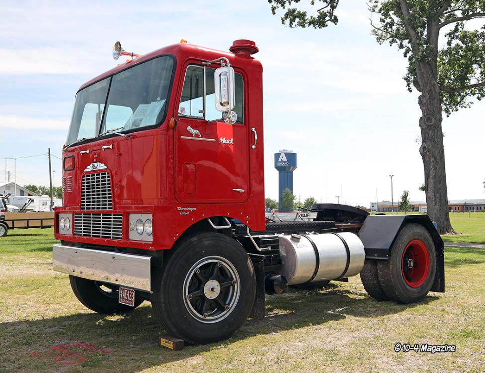
Came across this video on YouTube "Carrier or Killer" It is a truck driver safety movie made in the mid 1960's by the same company that made the drivers education movies "Signal 30" and "Mechanized Death" that we saw in class in the 60's. Neither the B Mack or the driver made it out alive. Quite a few other trucks from this period in the film too.
-
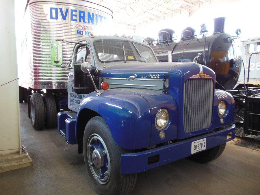
How about this Overnight Mack? Was my B-42. I sold it to Overnight about 20 years ago and they painted it in their livery as their heritage truck.

-
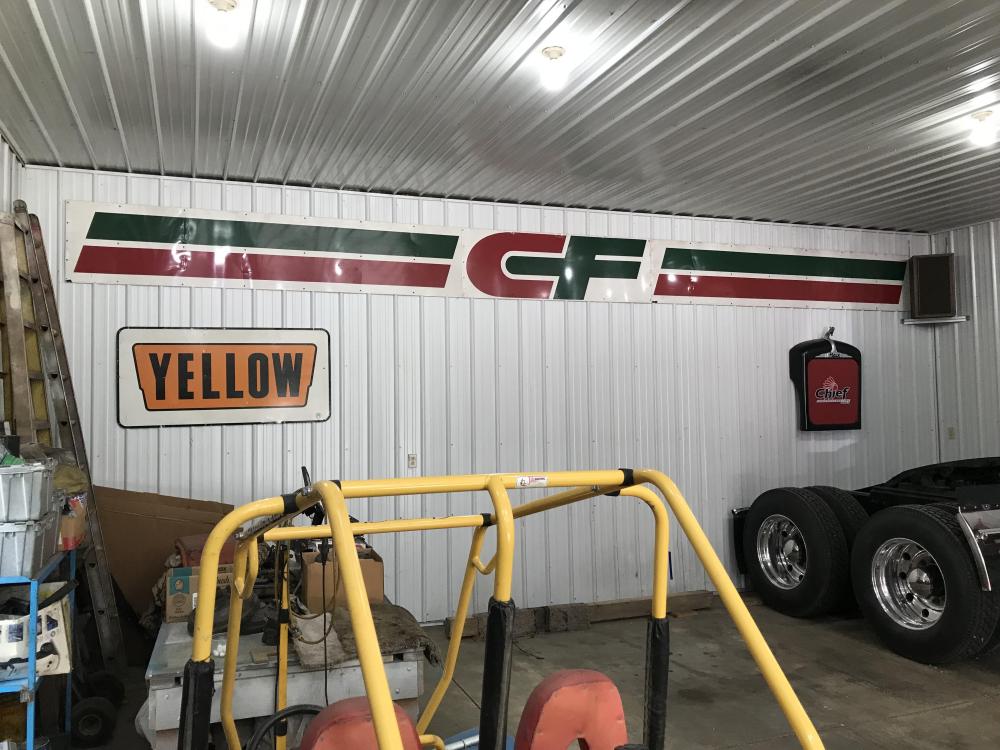
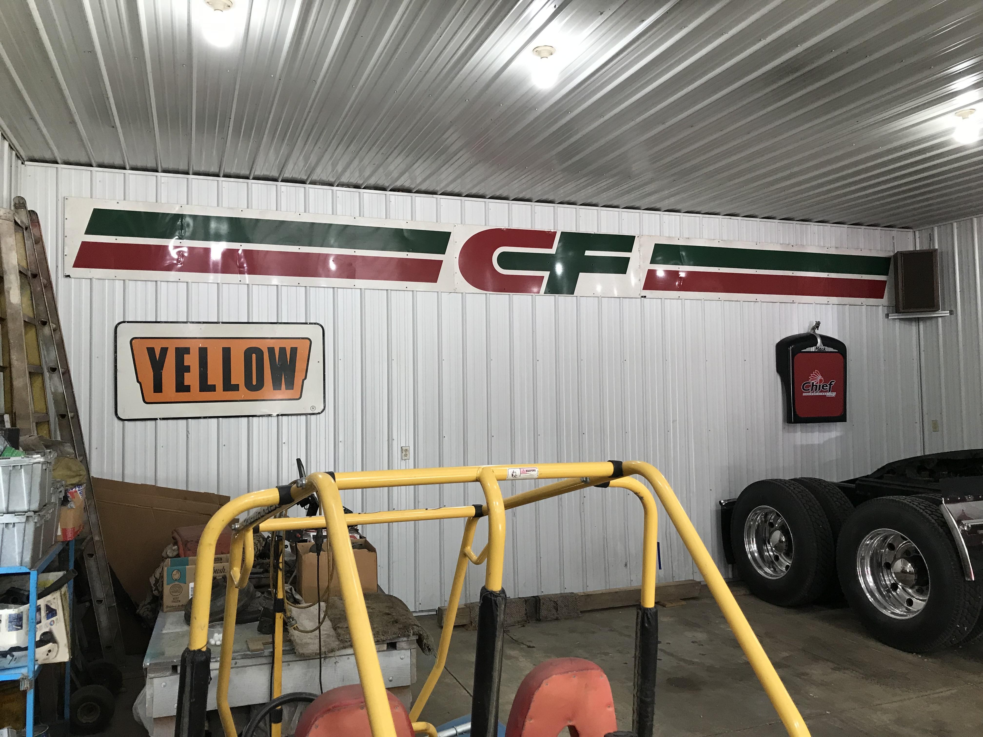
Spent a total of 36 years with both CF and Yellow. Was fortunate to be long gone from each before they went belly-up. They were great fleets in their day. Learned a lot from both. Sorry to see Yellow go, but the writing was on the wall since 2003 when they bought Roadway and USF Holland and went 1 billion $$$ in debt.
-
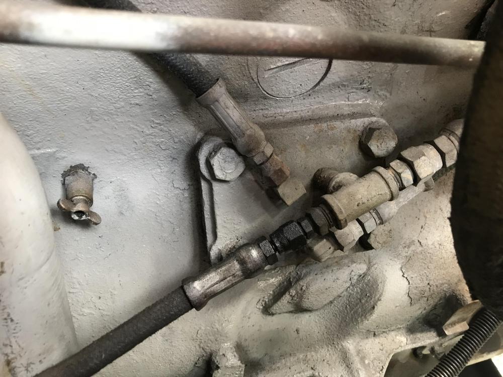
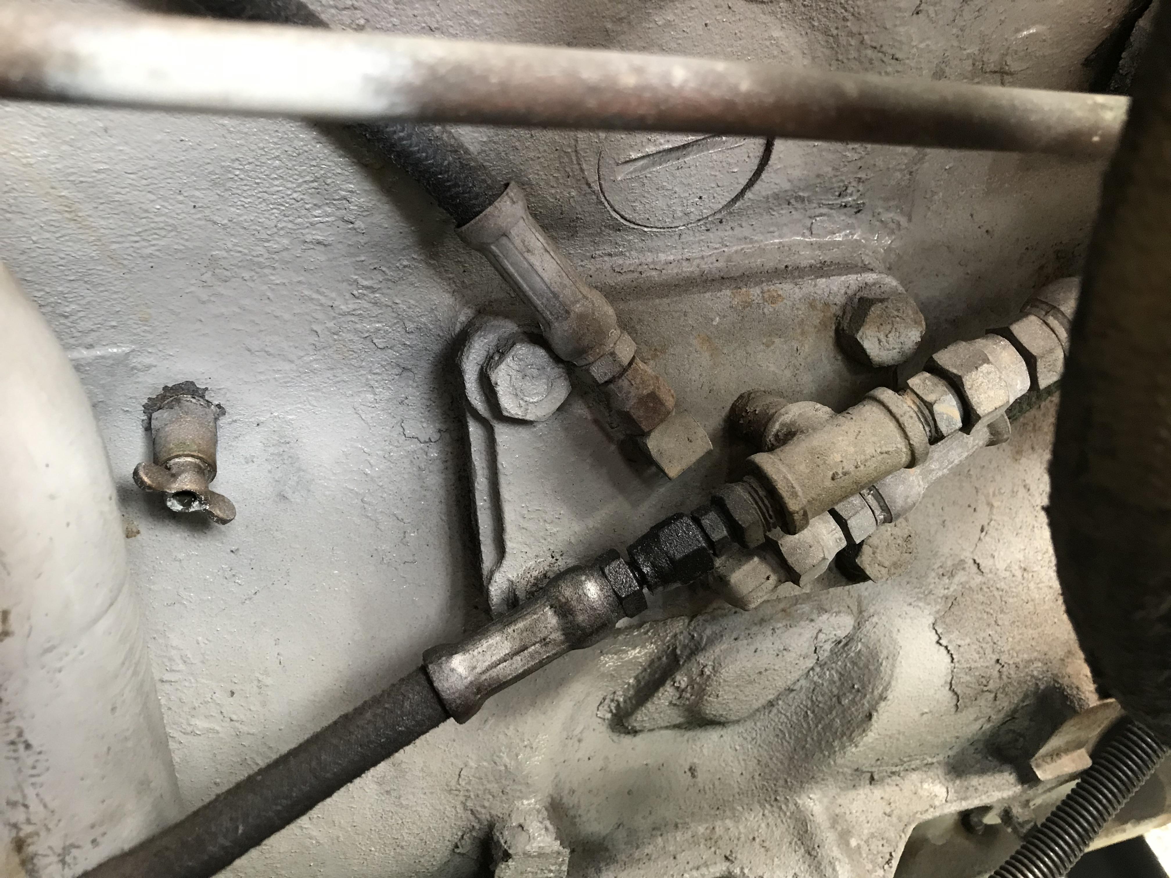
My G-75 has the END673 engine. Fresh 15W40 Delvac oil , clean screen in the pan, no visible signs of excessive wear when I pulled the pan, new 750 style filter in the can. Running when warmed up at highway speed have 25 PSI and idles at 5 PSI. Truck has a WGB model WB-2 Oil Clarifer bypass filter. The truck build line sheet shows a 485GB filter assembly installed at the factory. Don't know if these are the same. Anyway, I have included a photo of the oil distribution plate on the left side of the engine. The small line coming off the T goes to the OIL PSI gauge and the larger line to the rear goes to the oil filter. (Is this the proper location for the Oil PSI gauge?). The bottom line partially hidden under the T is the return from the filter and dumps back into the pan. I suspicioned that there was excessive flow through the filter and the oil pump could not keep up. I removed the filter feed line and blocked it off. Started and ran the truck up to temperature. Oil Psi at idle is now 15 and 40 at highway speed. My question is does anyone have info or literature on the WGB oil filter. Is there a restrictor fitting or metering orifice in this filter assy?? Also in the photo, the #4 line running up to the left goes to external oilers to the rockers. This could be another source of excessive oil flow demand reducing PSI. I'm going to pull the valve covers and see if the rockers are oiling without the external feed and possibly delete this feature. Any ideas on this??
-
Battery box latch
D2Denny replied to Robo987's topic in Antique and Classic Mack Trucks General Discussion
Same as 30 - 31 Model A hood latches. Get them in black or stainless about $15.00 at Bratton's, Snyders, or Gaslight -
END 673 oil PSI regulator spring
D2Denny replied to D2Denny's topic in Antique and Classic Mack Trucks General Discussion
Low PSI when warmed up. My Mack manual says 29.5 lb at 3 7/8 inches. Had pan down all looked good. No sign of brg material in pan sump or in filter. Regulator spring is next easiest avenue to pursue. -
Anyone know of a parts supplier that might still have on oil PSI regulator spring? Called Watts and no luck. Was able to get a part # 572GC110. Have the Mack specs on this spring, so if I can't find a new one I'll check it and shim to the correct height and poundage.
-
Coca Cola LJ Mack colors
D2Denny replied to 1961H67's topic in Antique and Classic Mack Trucks General Discussion
Here is a tip on your wood floor. When I built my hot rod, I opted to put a 3/4" marine plywood floor back in. If wood was good enough for 4 million Model A's it would be good enough for me, plus it gives the car and floor a more solid feel. For the bottom side of the plywood I obtained a sheet of 22 gauge pre-painted steel siding metal from our local barn siding manufacturer. (They have rolls of this stuff in various colors that they roll into corrugated barn siding). Using 3M contact adhesive in a spray can, I sprayed both pieces, let it tack up and bonded them together. Once the floor is installed and bolted down it looks like a steel floor from below, sheds water, and is easy to clean oil and grease from. Top side got the dynamat, padding, and carpet treatment. Sure helps to keep the heat and noise at bay. -
I need a new rear end
D2Denny replied to D2Denny's topic in Antique and Classic Mack Trucks General Discussion
OK. As previously mentioned, I have a 36" driveline. That is the distance between the Transmission output yoke and Diff input yoke. Obviously, the auxiliary boys know something I don't. Can you direct me to an auxiliary box to use that is so super short in length, that I can fit it in the allotted space (36") along with its input and output shafts, the required 4 u-joints, and a slip yoke, and still maintain adequate articulation to allow for rear axle suspension movement? From my recollection a Spicer 7041 is close to 24" long from its front companion flange to the center of the rear yoke. That would only leave me 12 inches to install the two connecting drive shafts and required slip yoke. -
I need a new rear end
D2Denny replied to D2Denny's topic in Antique and Classic Mack Trucks General Discussion
G model Macks were produced 4 years 1959 - 1962. A total of 2181 were built with 318 being G-75's 67Rmodel: If you could provide a name or contact # for the Va. place I'll give him a call. If its in the Wytheville Va. region I could turn it in a long day. Thx Dennis -
I need a new rear end
D2Denny replied to D2Denny's topic in Antique and Classic Mack Trucks General Discussion
67Rmodel Thanks for the response. I have reached out to both firms with a request for a feasibility assessment and ballpark cost. We'll see what response I get. In any case I wouldn't take this route until next winter as I doubt that this could be accomplished before show season. As to replacing the entire rear assembly as some have suggested, (I hate to be a wise guy) but please refer to the last sentence in my original post. I didn't want to list the litany of reasons for not doing a complete axle swap at the time. I have already gone through the wheel ends in regards to brakes and seals. I want to retain the 24.5 Dayton hubs and rims It has to be a top loader for driveline requirements with an acceptable ratio Chances of finding a "drop in" complete axle assembly to fit my requirements are about as slim as finding just a carrier assembly. I understand upgrading the entire rear unit is certainly possible and within my skill set, but the time, effort, and cost is not justified for a truck that might be driven 500 miles a year. If i need to go a distance with this truck it will go on the trailer and I'll go down the highway at 75MPH in air conditioned comfort dragging it behind my Autocar. I have to believe there is a CRD91 carrier out there somewhere with an acceptable ratio. -
I need a new rear end
D2Denny replied to D2Denny's topic in Antique and Classic Mack Trucks General Discussion
67RModel: I have called Adelman's some time ago. The parts man had never heard of a CRD91, let alone having one on the yard. As for having a new helical ring gear and pinion designed, machined from scratch, and properly heat treated, I really can't see this being cost effective. However if you could provide me with the name of one or two firms that you know of that provide this service, I'll give them a call on the feasibility and cost of this endeavor. Dennis -
I need a new rear end
D2Denny replied to D2Denny's topic in Antique and Classic Mack Trucks General Discussion
Matt: Thx for the reply but I shot that angle a while ago. The 91 series has a totally different mount bolt pattern and size than the 92 and 93 series. Also, the axle shaft spline diameter is larger on the 91 series. -
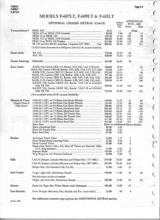
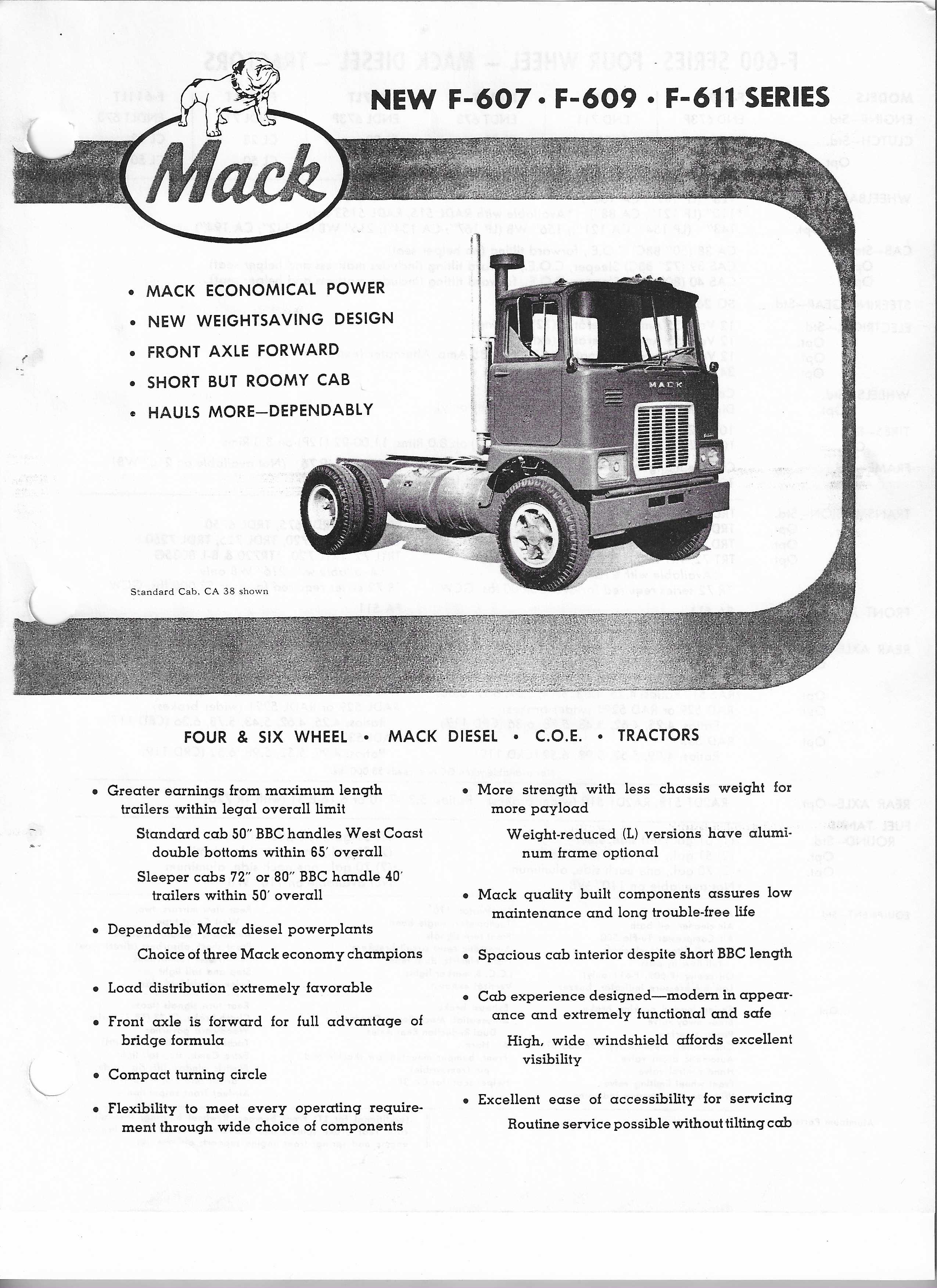
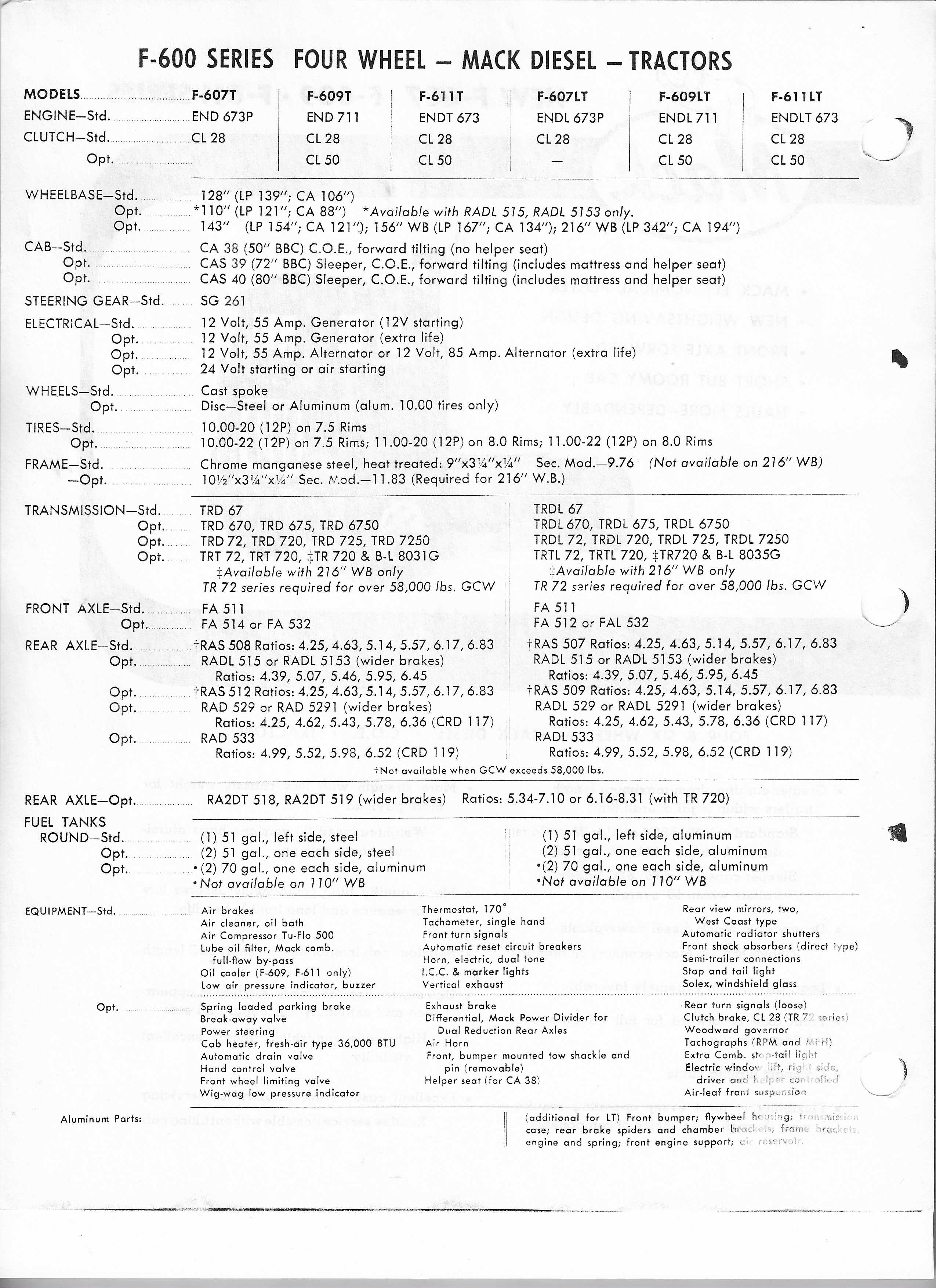
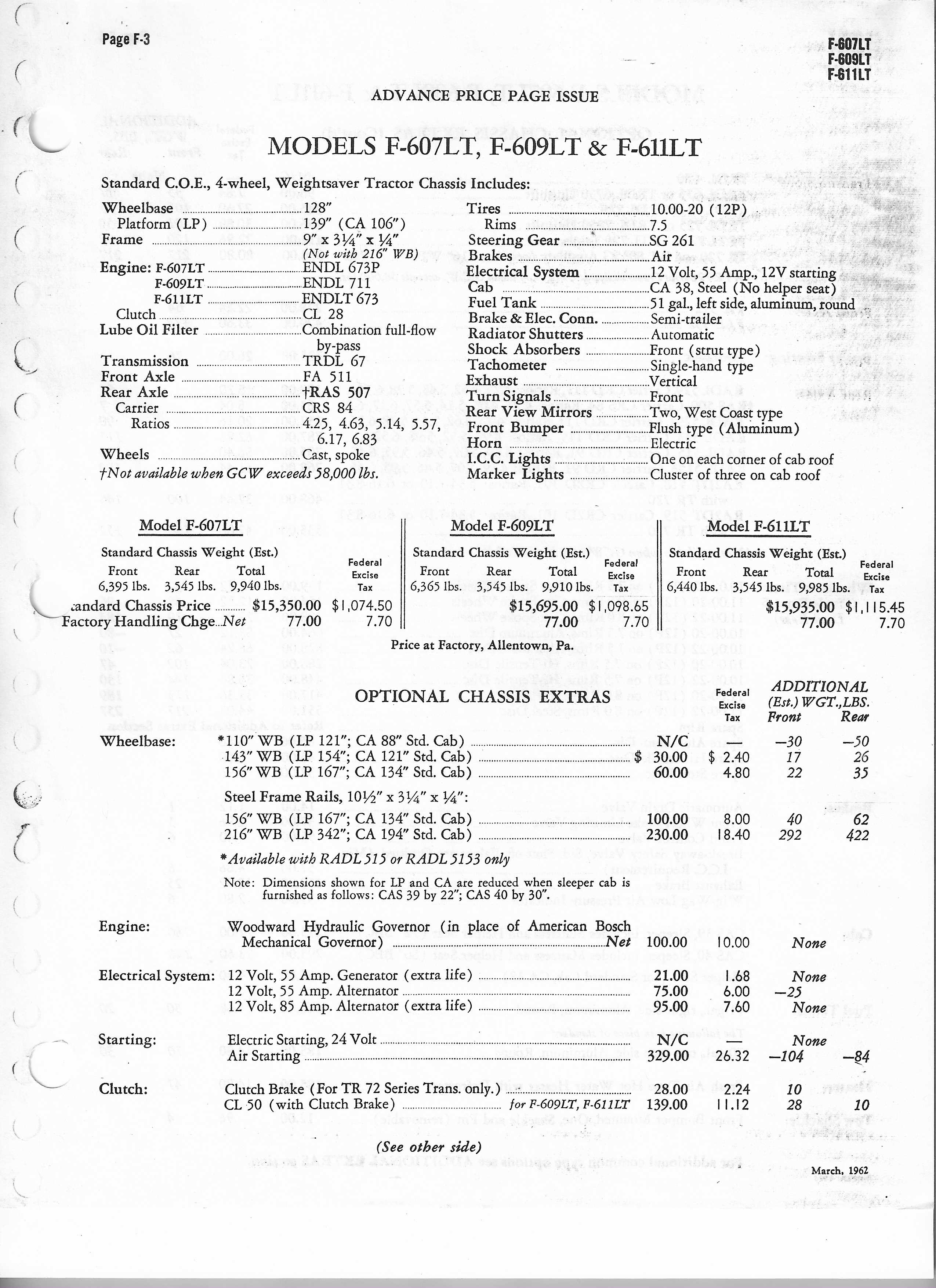
I have a several hundred page Mack Salesman's book from the early 60's. In searching out other models that have a RADL 515 rear, I came across these pages on pricing for the then newly announced F Model. Enjoy!


-
I need a new rear end
D2Denny replied to D2Denny's topic in Antique and Classic Mack Trucks General Discussion
The CRD91 carrier is a top loader. With the short wheelbase and length of the triplex trans, the driveline is only 36" long. A front loader carrier would drop the diff input shaft about 1 foot. This would make for an untenable driveline angle. Thats the reason Mack used this rear axle assembly on the original build. -
My G-75 came from the factory with a RADL 515 drive axle and CRD91 carrier assembly. The ratio is 6.45. Even with the TRTL720 trans and tall rubber, it maxes out at 60 MPH against the governor. The other ratios available were 4.39, 5.07, and 5.46. I checked with all the truck junk yards within 50 miles of North Central Ohio and no luck on a possible replacement with a better ratio. I checked with several of truck gear unit rebuilders to possible re-ratio it, but no parts are available for this carrier anymore. Anyone know of any possible sources of a replacement CRD91carrier in Ohio or half way into the surrounding states? Replacing the entire drive axle assembly with a later model top loader to get a better ratio is not an option at this time.
-
In the late 70's CF transitioned from the 855 engine to the VT903 in our Line Haul tractors. Early on, there were cam follower and cam failures. This was due to fuel dilution caused by leaking injector o-rings. The root cause of this was that the Injectors were secured by only a single bolt crab style hold down. This and the harmonics and vibrations of the V8 caused the o-rings to flatten out and pass fuel into the engine. The problem was solved by incorporating an injector o-ring change into the PM schedule. I believe it was somewhere in the 150,000 mile range. As a side note, as we were working through this problem, we were talking to the Cummins engineers and they were telling us of the 1200 HP 903's that were used in army combat vehicles. This was full military power. When they were questioned on the longevity of such an over fueled engine their answer was the Army told them the average time a tank survived in a tank battle was 20 minutes so they needed the engine to last a little longer than that. As for me I always preferred an inline 6 cyl engine but the 903 was far superior to the 6v-92 that CF was transitioning to from the 8v-71at about the same time.
-
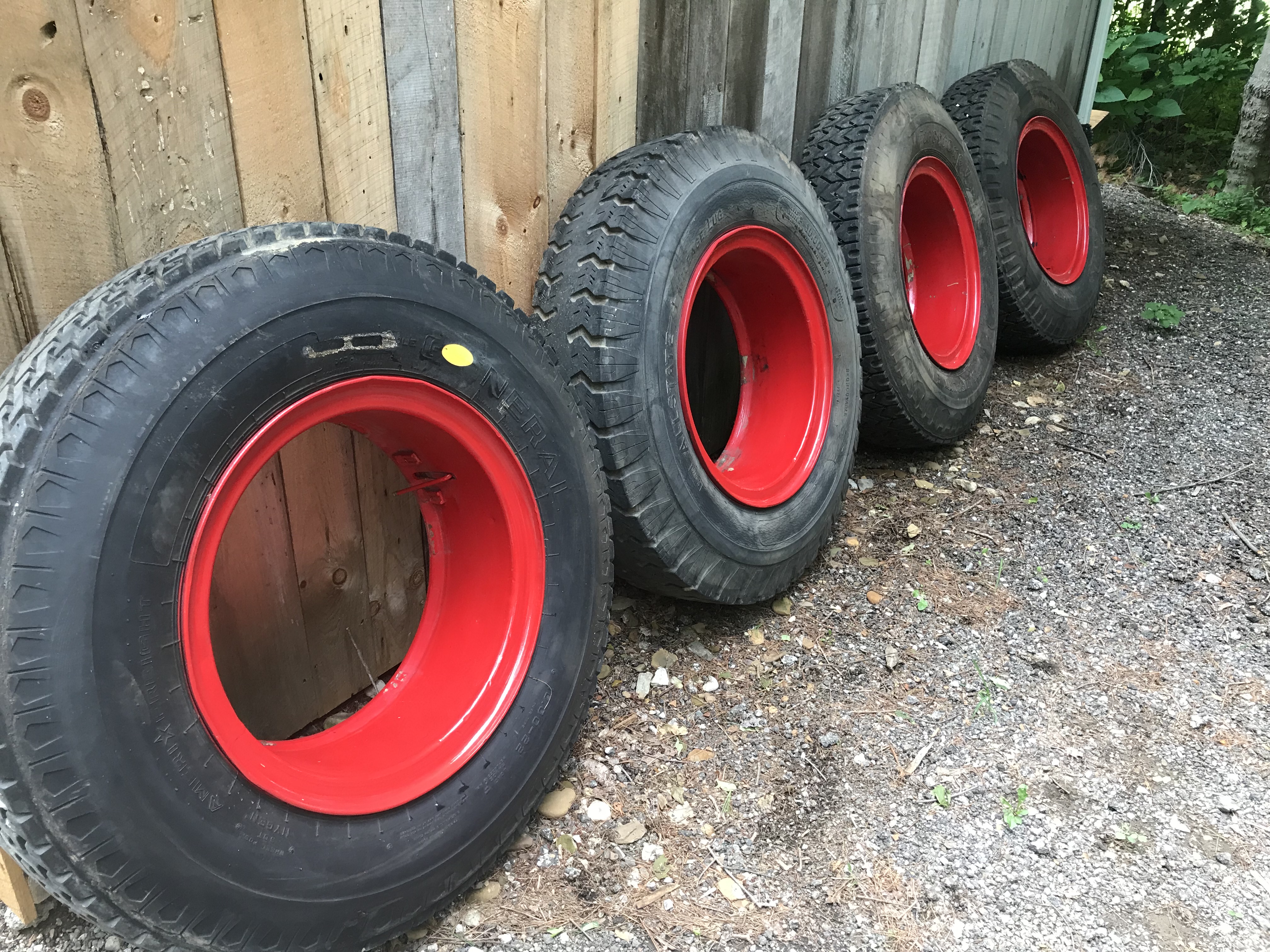
4 10X22 rims and tires removed from my G-75. Rims in really nice condition. Tires are 40 years old, They are hard round and black with 30% tread. $100. for all. located in the Mansfield Ohio area Dennis 419-545-2706

-
- 1
-
-
END673 in pan oil screen
D2Denny replied to D2Denny's topic in Antique and Classic Mack Trucks General Discussion
This truck only has a bypass oil filter with a 750 type element in it. So at this point nobody is sure how the screen was installed in the oil sump?? -
Went to change the oil in my G-75. Decided to pull the bottom cover in the pan to clean the screen. Removed cover and found no screen. Looking into the removed cover I see the remains of 4 spot welds. Was the screen detachable or was it welded to the cover? Going to have to pull the pan as the tin cover or shroud at the bottom of the oil pump and pickup tube is cracked. Don't want it to completely fall free and potentially block off the flow to the pump.
-
B613T ENGINE
D2Denny replied to skydawg's topic in Antique and Classic Mack Trucks General Discussion
Here is a tip on pressurizing a fuel system: Cut an 8 or 9 inch circle around the valve stem in an old innertube. Secure it to the fuel tank filler neck with a large hose clamp. Pressure the tank up to 5 to 8 PSI through the valve stem and bleed the system. I have done this numerous times both on trucks and old Cat equipment. I keep one and an assortment of clamps in my traveling tool box.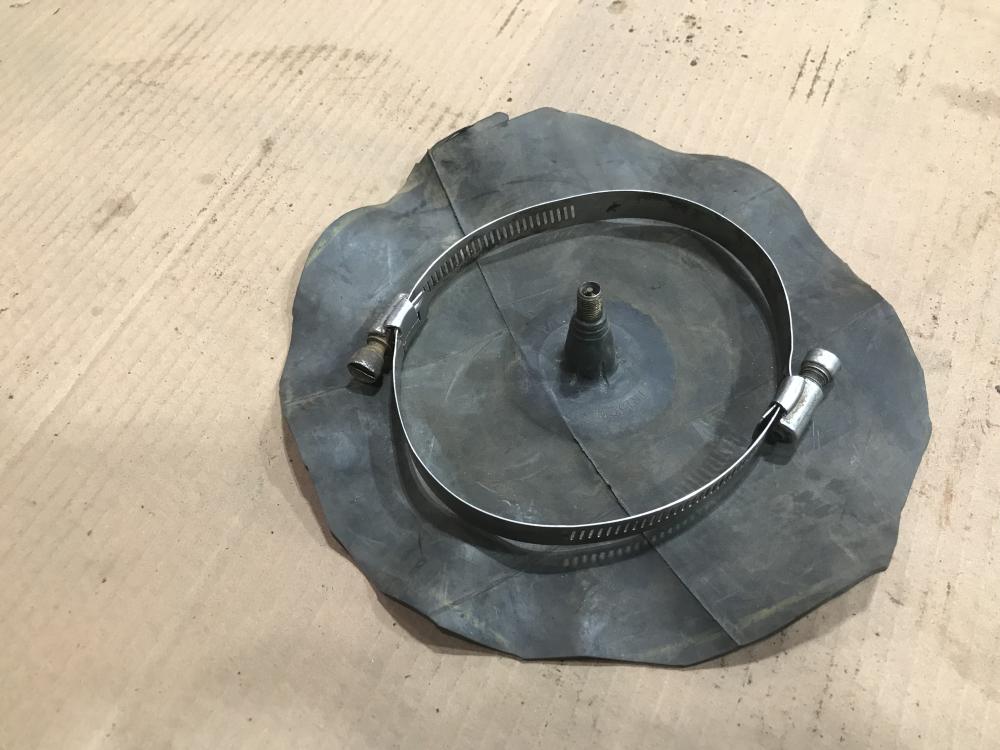
-
Wheel seal part numbers
D2Denny replied to D2Denny's topic in Antique and Classic Mack Trucks General Discussion
6368 thanks for taking the time to look this up. However, the SKF seal listed fits a 4.375 shaft and my axle has a 4.875 shaft. The seal I got is a SKF 48769 -
Wheel seal part numbers
D2Denny replied to D2Denny's topic in Antique and Classic Mack Trucks General Discussion
Wow, lots of tribal knowledge here. Just the info I needed. Thanks Terry and Joey. I'll ditch the inner seal and I think I have zeroed in on a CR seal that will work.
.jpg.05e44ac1f6e7c64e744c001d55c56e4f.jpg)


BMT Forum Logo
